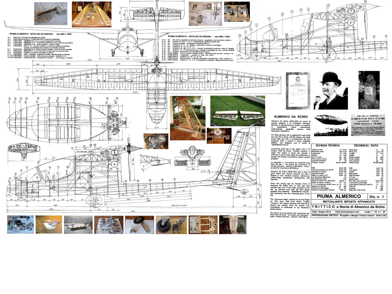
Piuma Almerico side-by-side two-seater
The Piuma Almerico two seater project was born as a search for better efficiency compared to the Piuma Twin Evolution, obtained with various modifications: the wing now has more glider-like profiles and has greater aspect ratio, the ailerons, flaps and
spoilers have been refined, while the fuselage is more streamlined and with a smaller section. This made it possible to reach an efficiency of 25, a remarkable goal for a side-by-side two-seater motor glider of amateur construction.
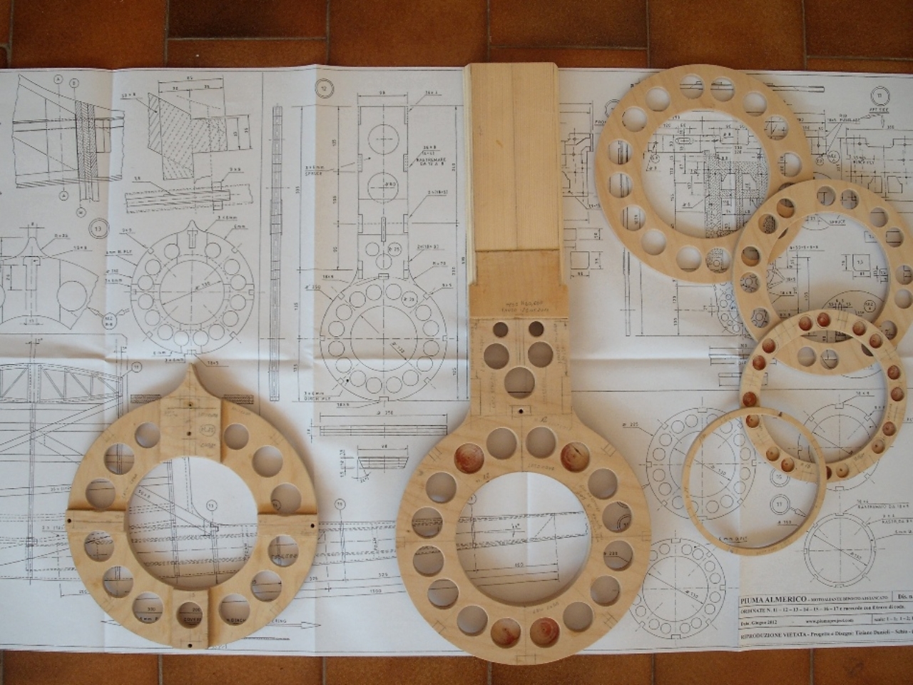
The result of the design, refinement and remaking of the new drawings, which lasted about 5 years, is summarized in the Project Book and in the Construction Book, as well as in the 25 tables completed in 2012.
Subsequently, the author then suspended the construction of the two-seater Almerico, introduced some modifications to make it single-seater (for personal use) and continued with the construction by replacing some parts already built.
Basic peculiarities
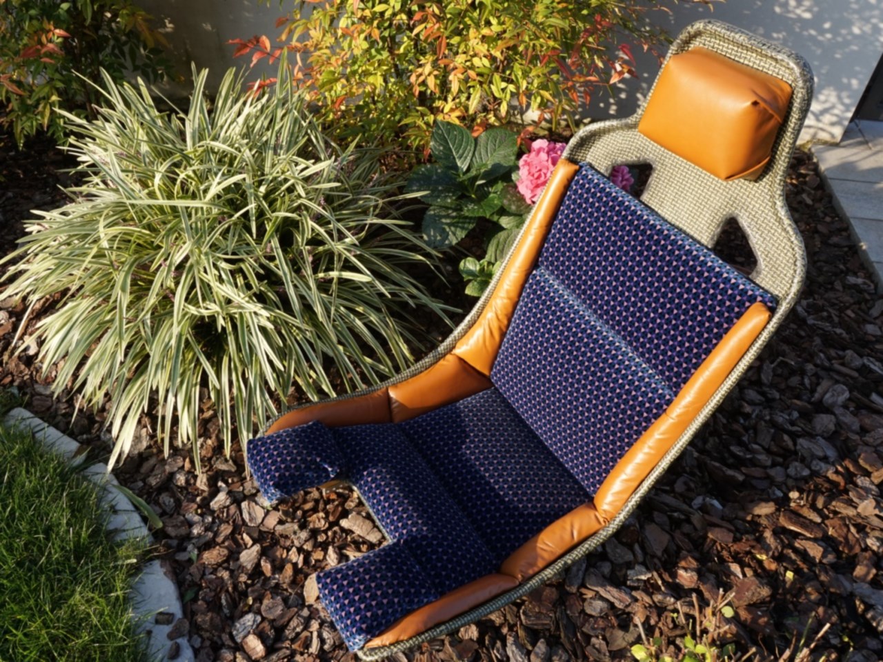
The Piuma Almerico is a side-by-side two-seater, with the front area low enough to allow a wide front and side view; the instrument panel is cantilevered like a glider, in fiberglass or carbon fiber, while the seats are in a more reclining and
forward position, padded and comfortable for touring use.
The wing is high and braced, the engine is propulsive and the landing gear, positioned in an almost barycentric area, is a leaf spring in a laminated ash and fiberglass mix, resistant and teardrop-shaped, complete with wheel fairings; a small front wheel,
which can be operated with the pedals, allows easy movement on the ground.
For mainly glider use there is an alternative narrow landing gear, retractable in the fuselage, which, at the cost of a few dozen more hours of construction, allows the gain of about 2 points of efficiency compared to the fixed landing gear; the author
has already made it but not used for the single-seater (if anyone is interested write me).
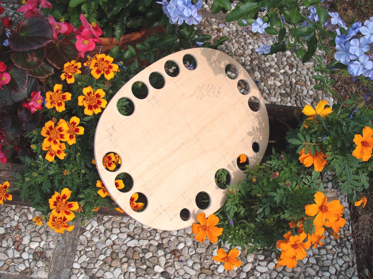
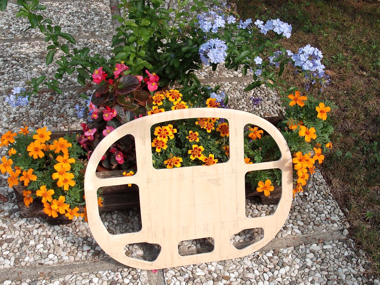
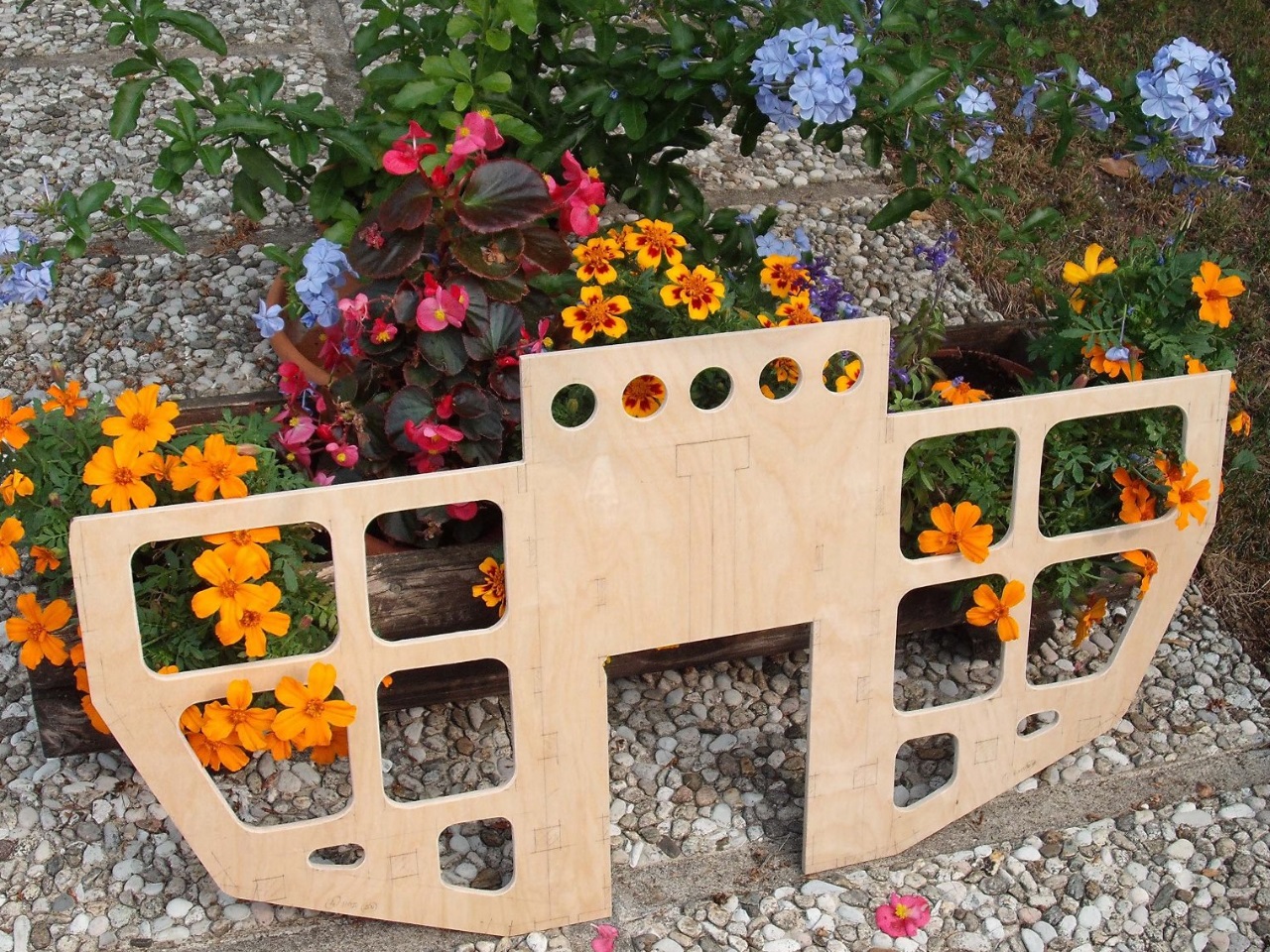
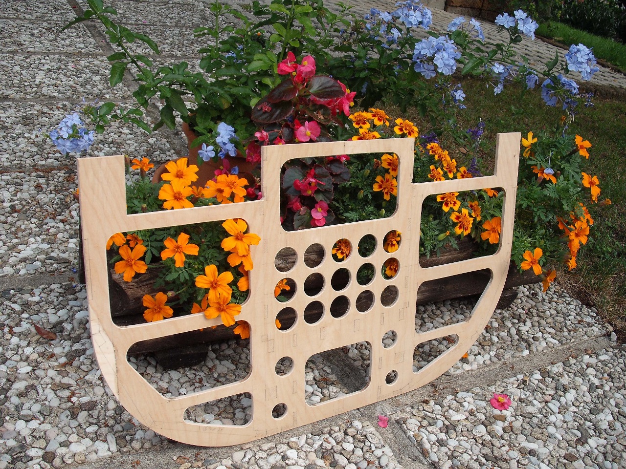
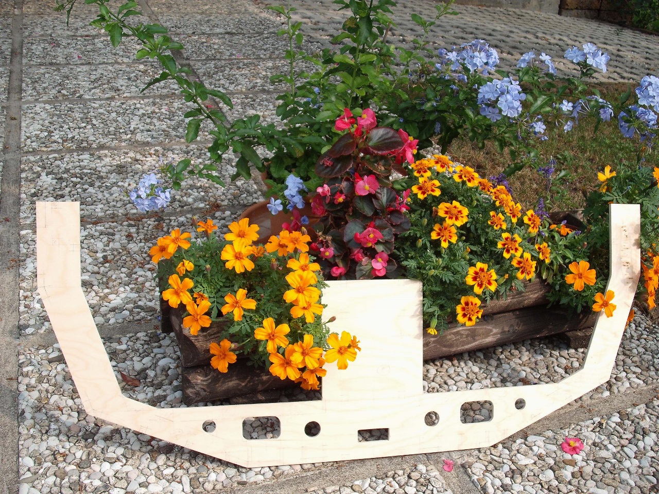
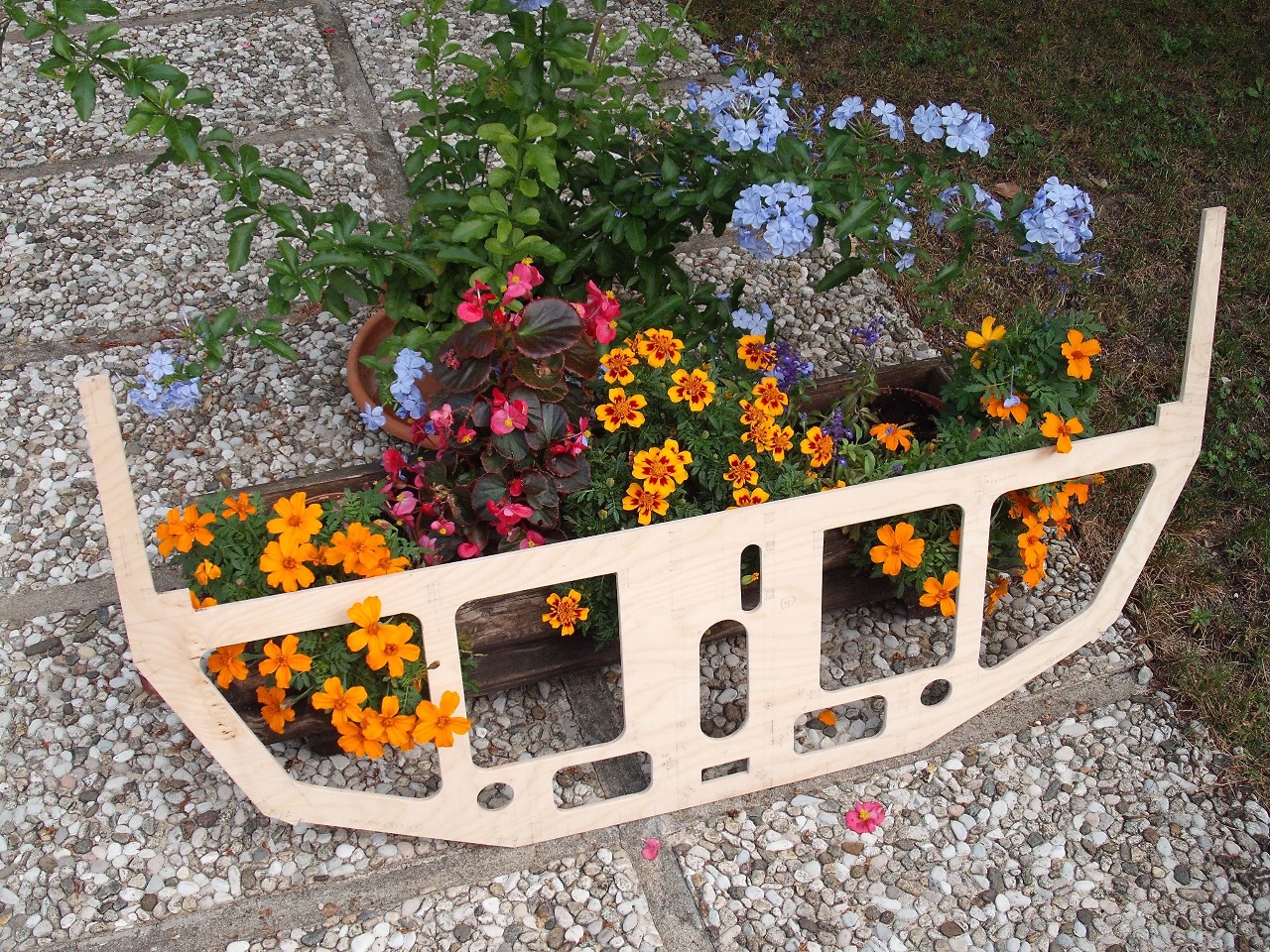
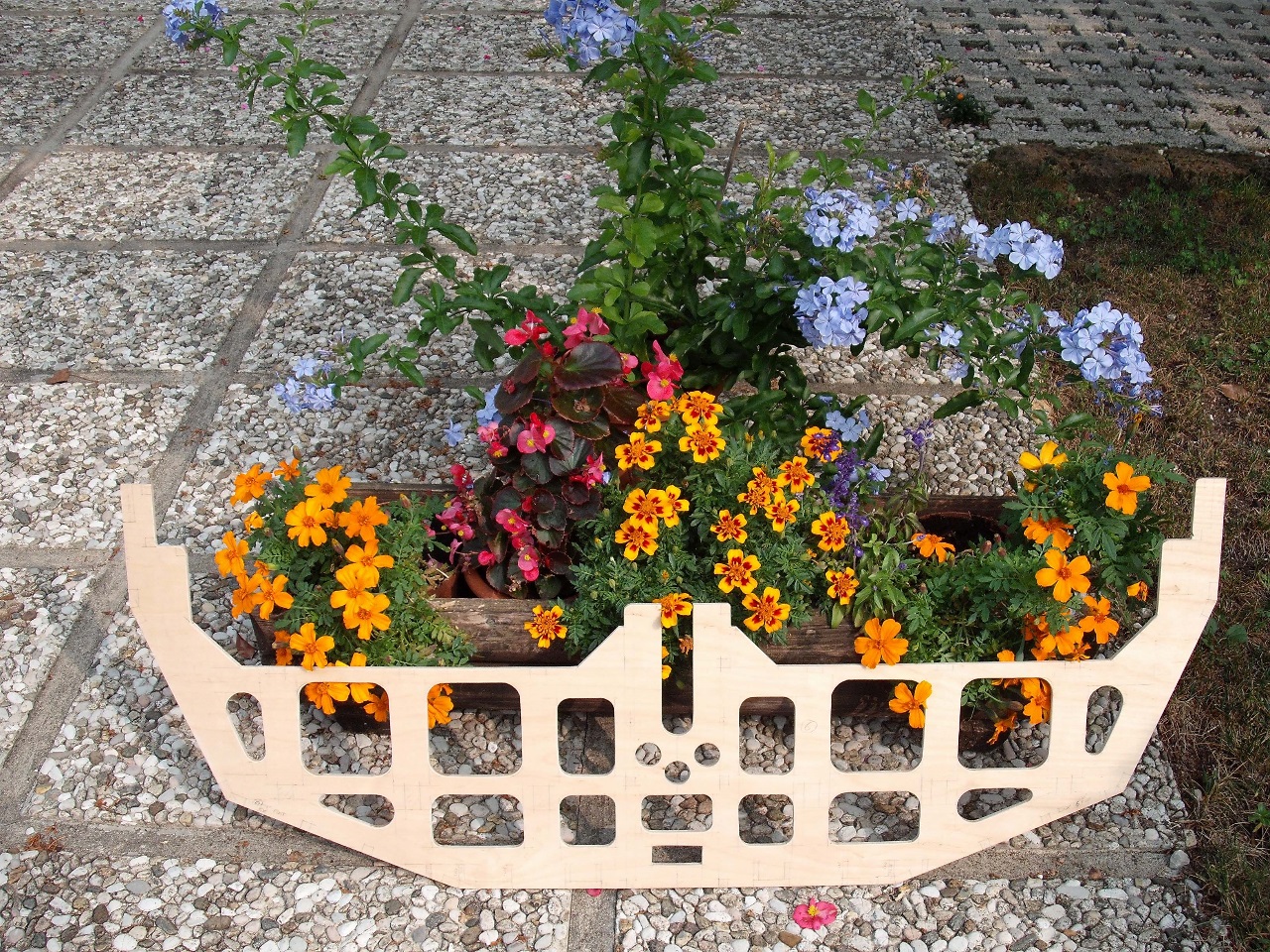
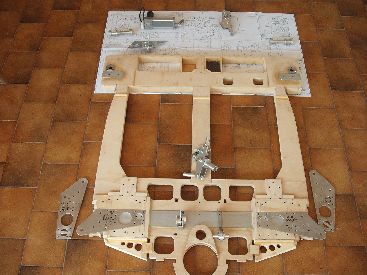
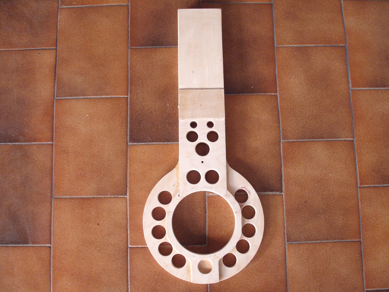
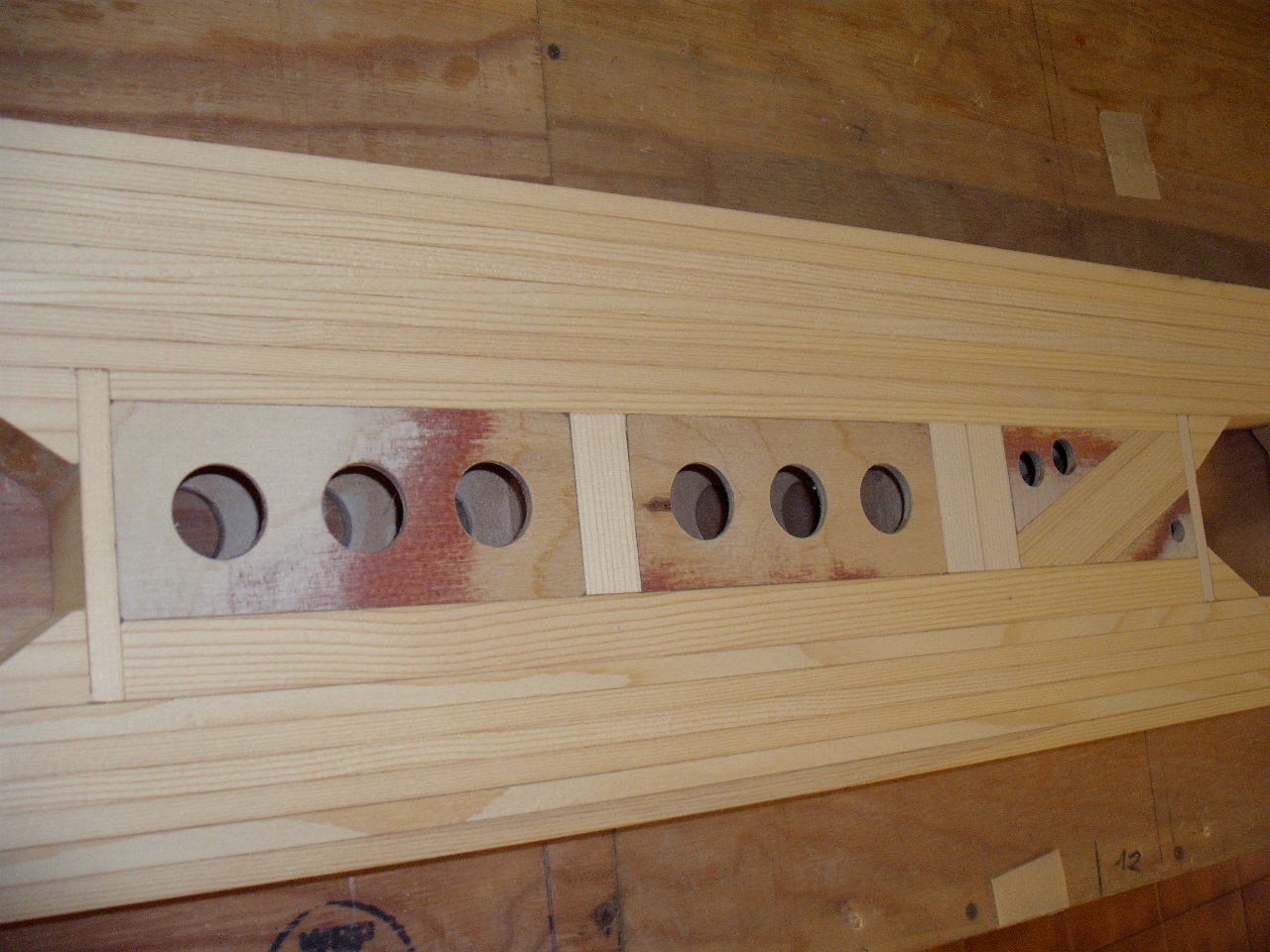
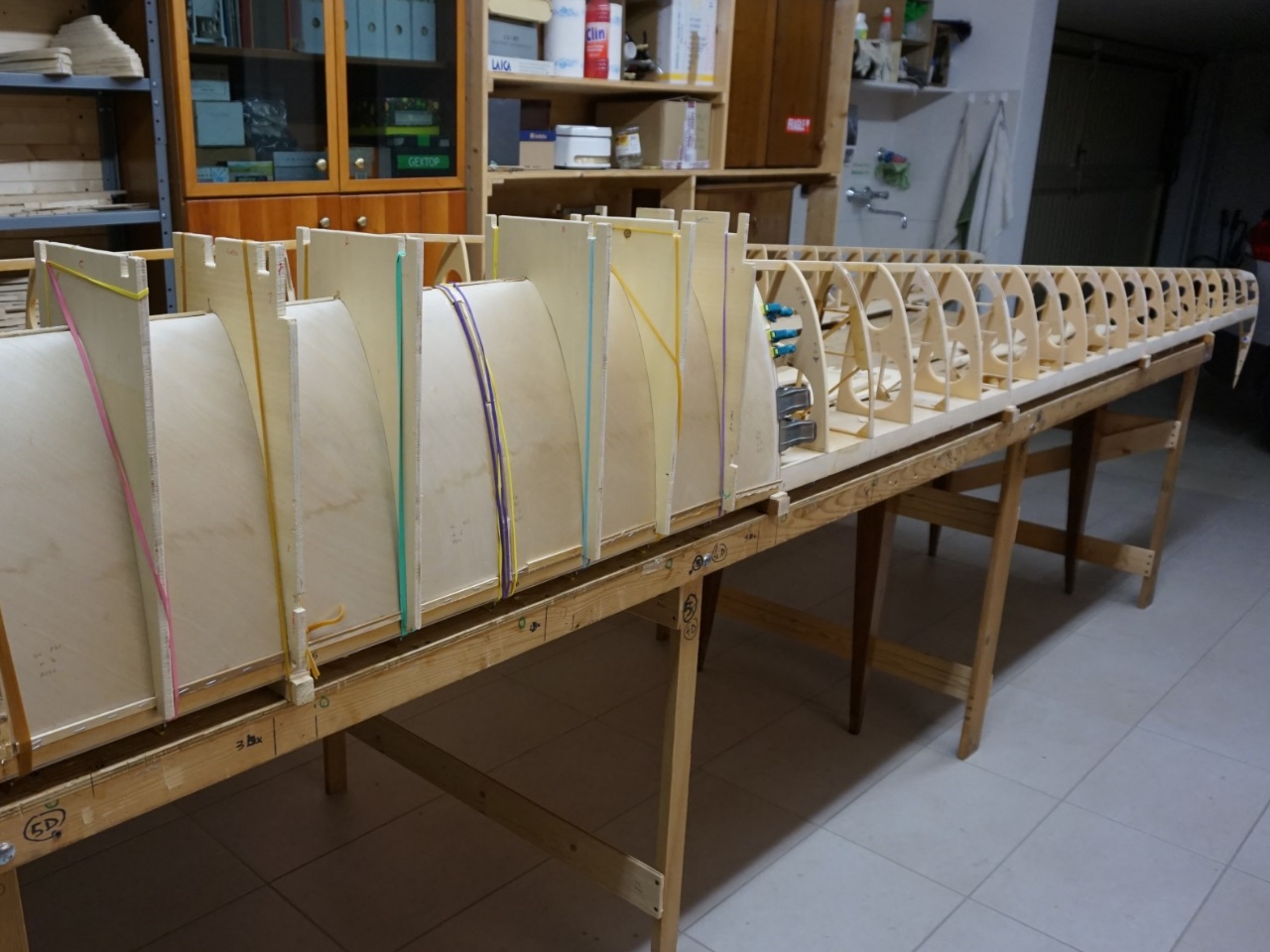
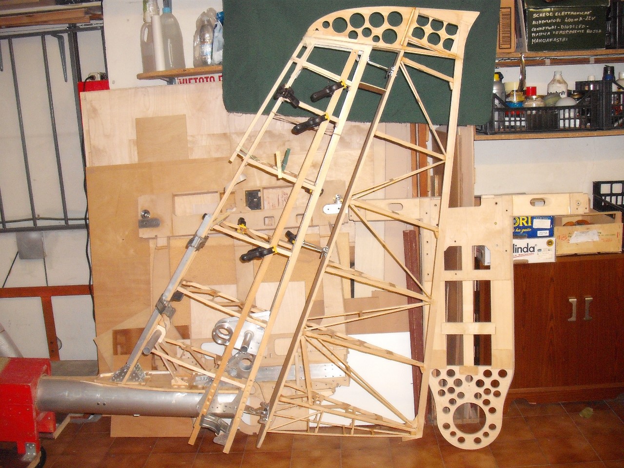
The numerous but light birch plywood fuselage frames give shape and strength to the whole and support the landing gear, the wing struts, the engine, the seats and the various linkages and drive mechanisms (cloche, flap motor, etc.).
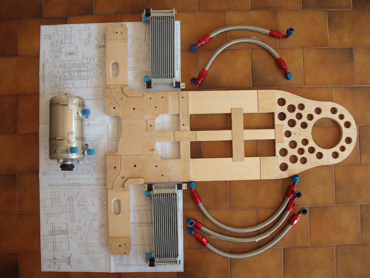
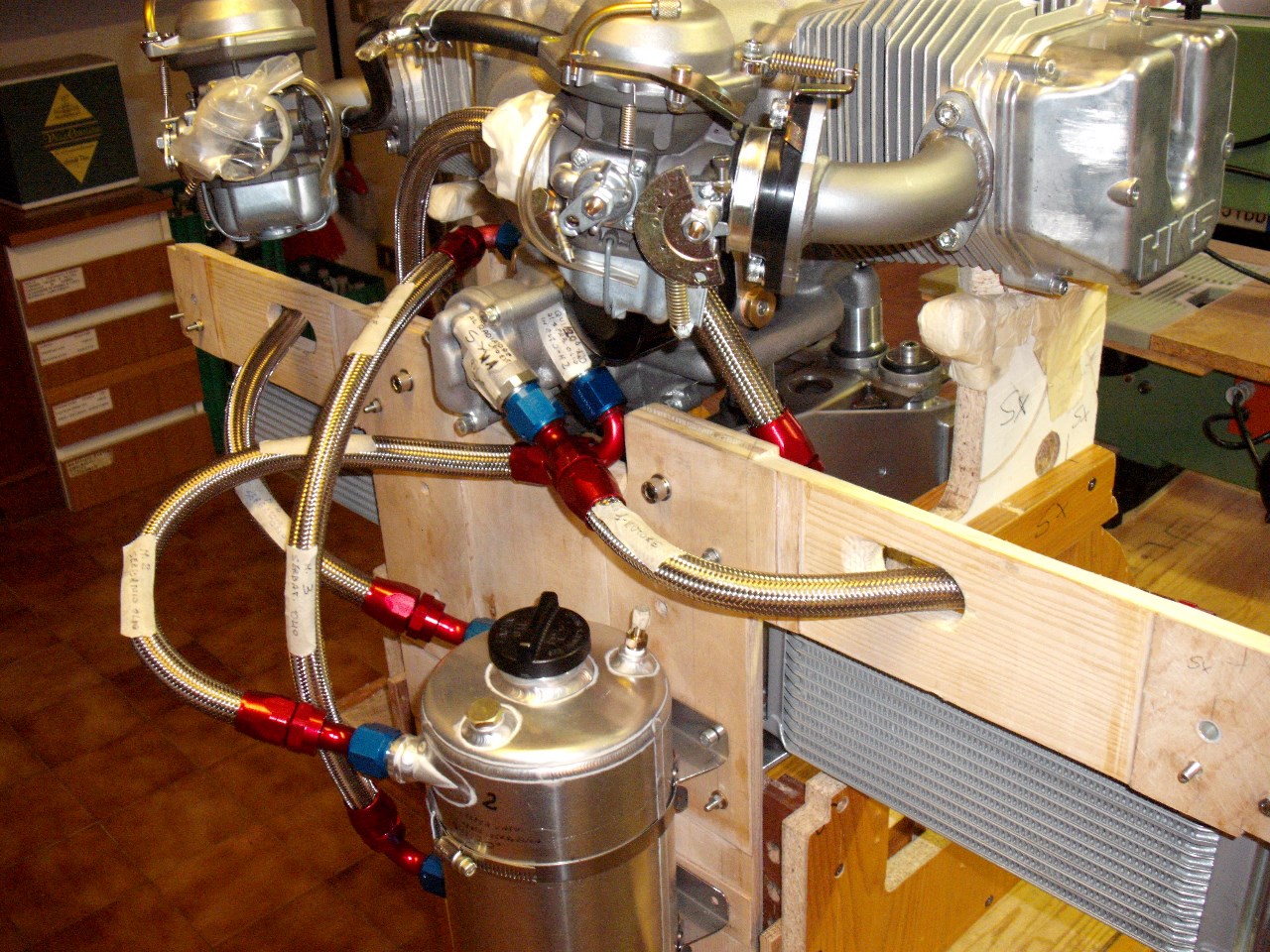
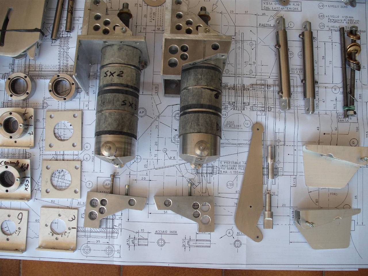
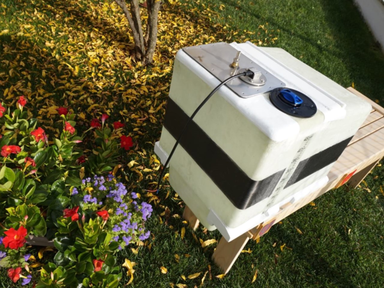
The engine used is the 60 Hp 4-stroke HKS 700 and the engine mount, oil cooler and oil tank, as well as the space for the small muffler have been designed for this engine, which is no longer in production; unless you find some used specimens, similar
engines in terms of weight (about 55 kg-122 lb) and power (60 HP) are recommended. However, it seems that the company: Quicksilver Aircraft Northeast - Light Sport Aircraft Sales- still ensures continuity for spare parts and still has some engines
available - info@quicksilverne.com
The use of a ballistic or pneumatic parachute has been foreseen with the attachment in the anchor plates of the wing struts; for its positioning it is advisable to make use of the experience of the manufacturer of the parachute itself.
Balancing with the rear-engine configuration may require ballast in the case of flight with the pilot alone; this must be checked during centering and in the extreme front area there is a space for shaped lead blocks.
Technical information
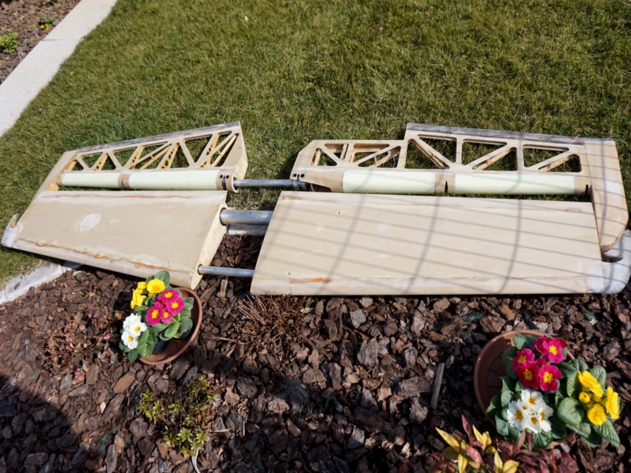
- Airfoil, chord and winglet: the airfoils are glider-like: FX 61-168 (16.8% thickness at 37% chord) at the root and FX 60-126-1 at the tip, twisted by about 3° negative ; the maximum chord is 1150 mm (45”).
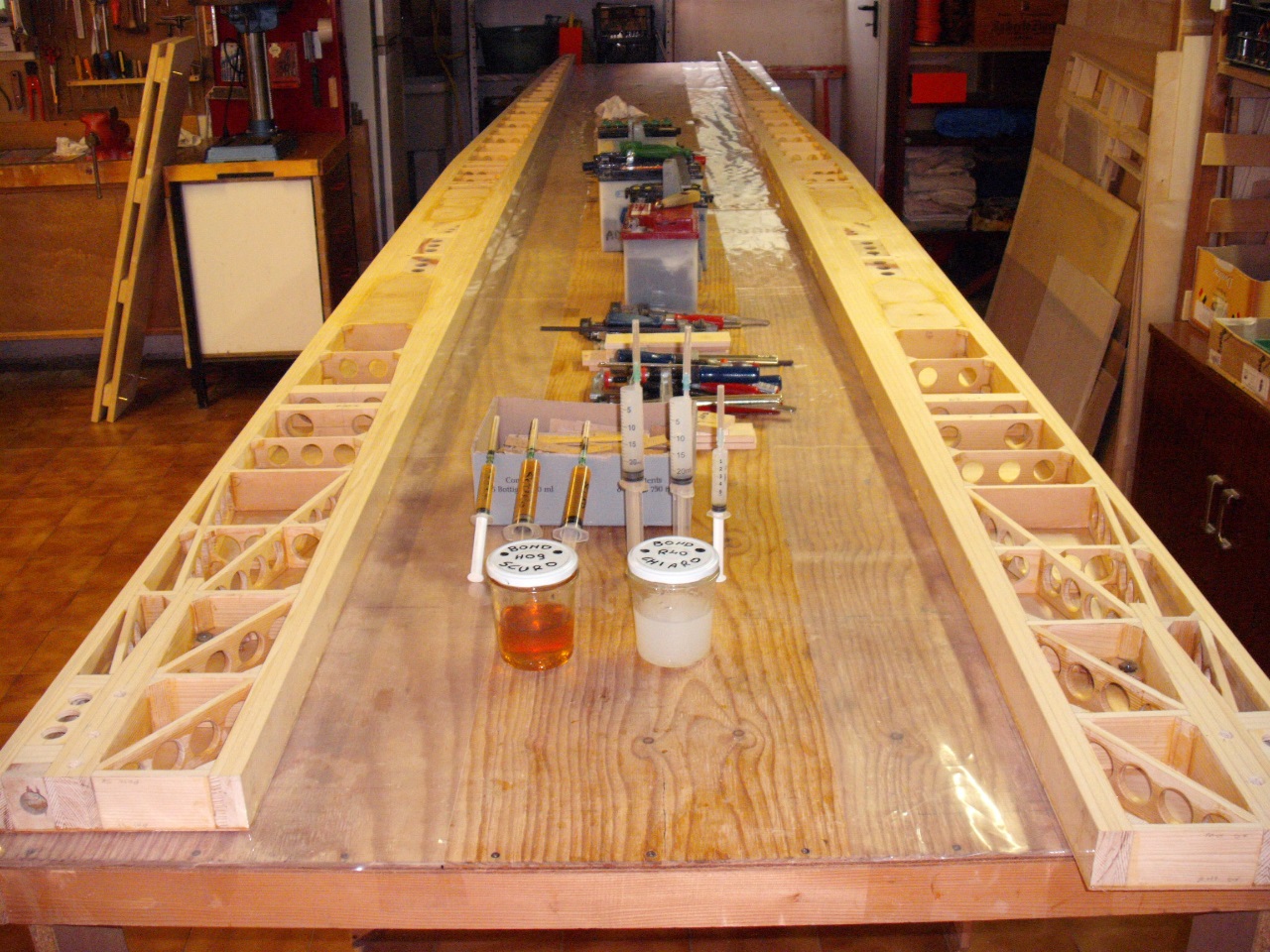
- The wing covering is in birch plywood with different thicknesses according to the area, with application at 45° and internal stiffening with styroform.
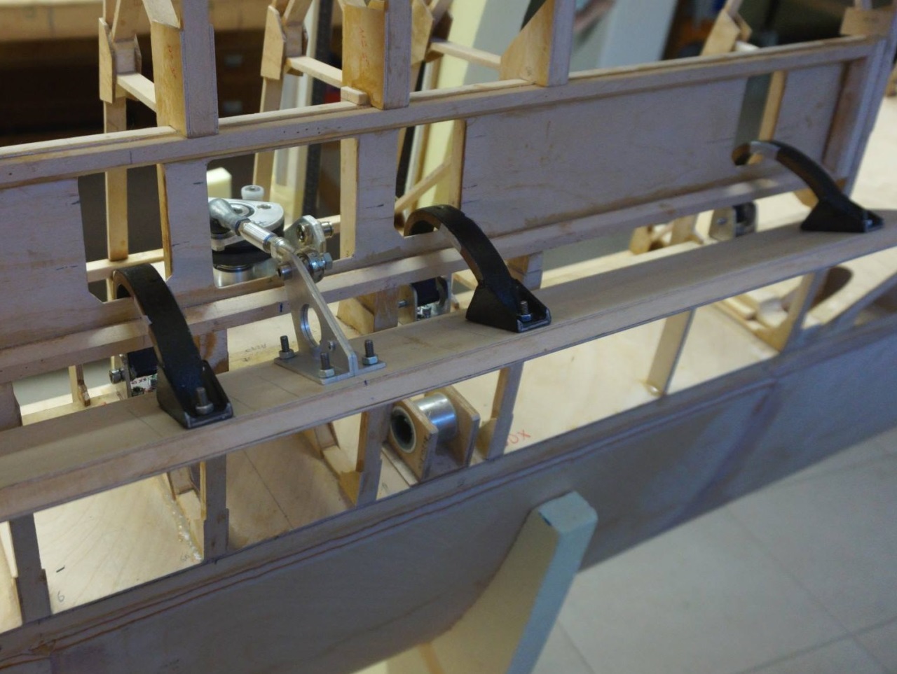
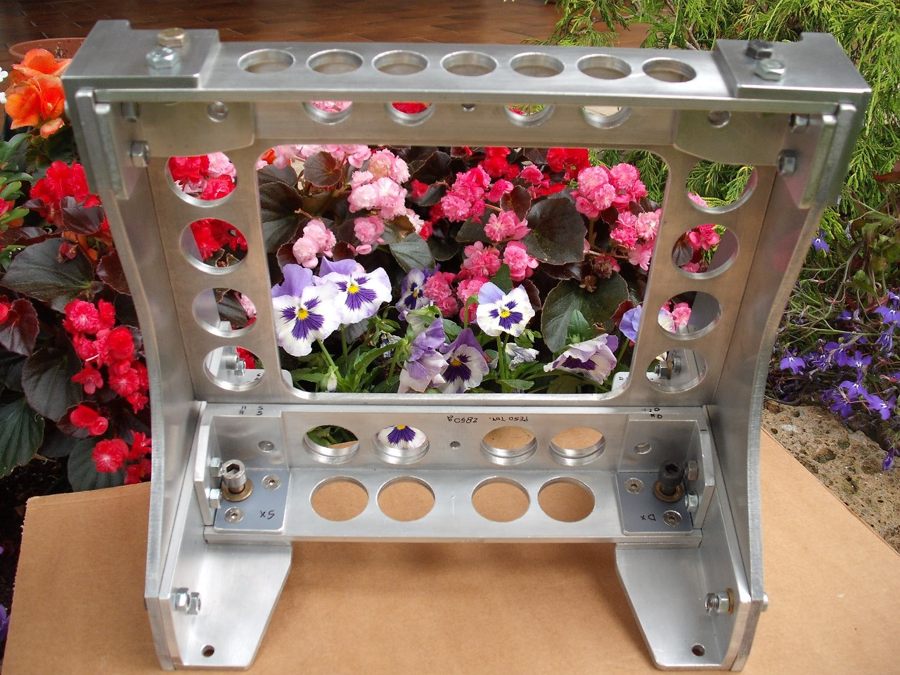
- Air brakes: they are positioned further back on the chord so as to influence less the displacement of the center of pressure during their use (less changes in attitude); the drive mechanism has been changed to have less effort and more
effectiveness.
- Ailerons: their action is with a rigid bar and the hinging is central rather than upper, therefore better aerodynamics and efficiency.
- Flaps: they are operated electrically by means of 2 bars (instead of 3 as on the Twin); they are smaller, but the slot system ensures excellent effectiveness.
Wing Span
Wing Area
Length
Height
Empty Weight
Gross Weight
Fuel Capacity
HP/HP (range)
V.N.E.
Top speed
Cruise
Stall clean
Stall full flaps
L/D max
Aspect ratio
Min. Sink rate (56 mph)
Load factors (breaking)
Load factors (security coeff. 2)
Take-off
Landing
Bldg Time (man hours) |
43 ft.
122 sq.ft.
21.3 ft.
6 ft.
600 lbs.
1000 lbs.
12 gal
60 (50/60)
112 mph.
110 mph.
90 mph.
44 mph.
38 mph.
26
15.4
200 ft/min.
+ 8 -2.2
+ 4 -1.1
500 ft.
500 ft.
1.400 |
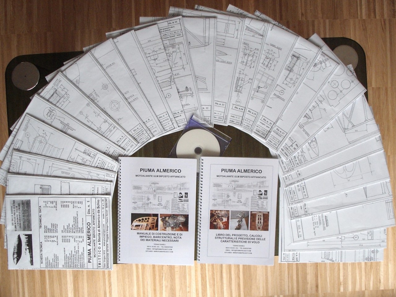
Construction Plans
The
Construction Plans consist of the following:
- N.25 detailed drawings large approximately 100 x 60 cm (40’ x 24’) , which describe both the normal version with the normal landing gear and the special version with retractable landing gear in the fuselage.
- The Construction Book is 56 pages (with 97 photos and drawings); it also contains information on wood, plywood, glues, aluminum alloys, Dacron, paintwork, general electrical system as well as instructions for trim and for flaps.
The first 10 pages are dedicated to materials and equipment, about 30 pages to the various parts to be built and to assembly; follows the detailed note of all the necessary materials, the calculation of the center of gravity and the instructions
for the first flights, as well as the check-list of the pre-flight checks and a hypothesis of weights for the parts to be built.
- The Project Book which in over 90 pages of calculations with more than 140 photos, tables, drawings and graphics, explains how the Almerico was born, verifies the sizing of the resistant structures, shows the verification calculations,
as well as those for the determination of the Resistance, Lift and Moment, from which the Efficiency at the various speeds can be deduced.
The VNE and VA are obtained from the wing torque calculations, while the various stall speeds are obtained from the Lift with and without the Flaps.
- Also included is a DVD with 3800 photos of the construction phases of the various Piuma, including the Almerico, many photos of the completed and flying single-seater and two-seater Piuma and some in-flight videos, as well as a detailed
note of all the necessary aluminum alloy construction parts.
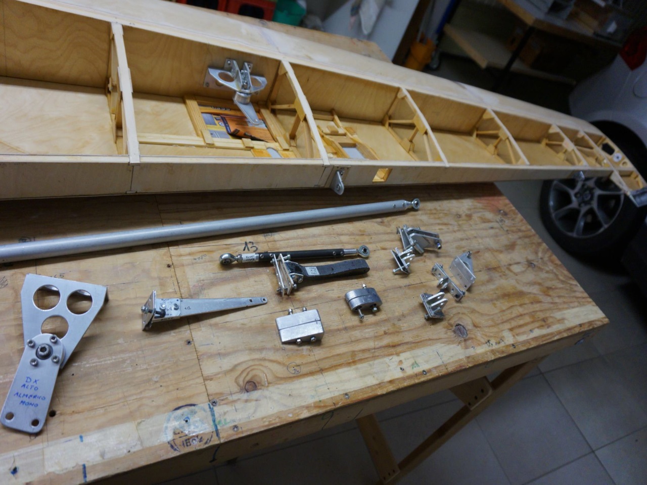
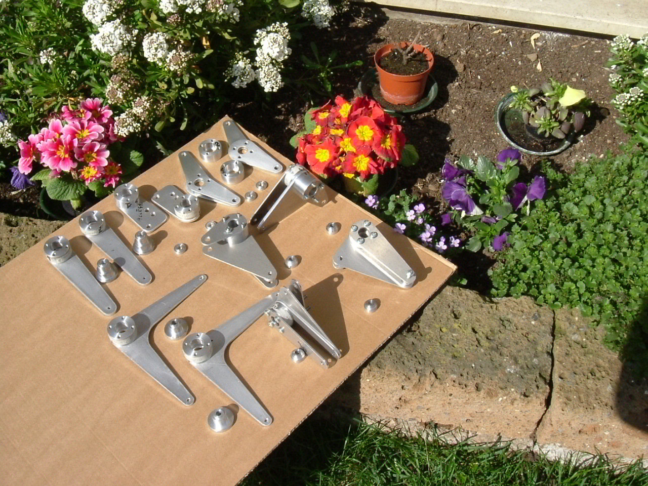
- Also included are the CAD drawings for water or laser cutting of all the flat metal parts, which can be made in these ways.
- There is also a file with the CAD drawings for waterjet or laser cutting of all the frames in avio birch plywood.
Other useful information for the builders also about the costs
Over the last 3-4 years, material costs have increased significantly, although the self- construction allows you to build an ultralight motor glider at a fraction of the cost of a similarly equipped industrial machine with the addition of priceless satisfaction of knowing every detail of the motor glider you're flying.
The
cost of the materials themselves (wood, tubing, sheet metal, dacron, glues, etc.), excluding the engine, engine instruments, avionics, and parachute is still modest and can be estimated at around $ 16,000 at 2025 prices.
For the engine, avionics and parachute, much depends on whether you're purchasing a new or used engine and whether it's a 2- or 4-stroke engine.
The estimate here is really difficult, but if we really wanted to hazard a guess we could think of adding another $ 14,000 for the 2-stroke engine and used instruments, or another $ 26,000 for a 4-stroke type HKS with engine instruments and traditional (non-digital) complete avionics like those visible in the photos of the dashboard of my Almerico one-seat build.
In summary, we will have a forecast of a total cost between $ 30,000 and $ 42,000 with non-digital avionics.
The tail boom is made of 6005-T16 aluminum alloy in the dimensions: diameter 127 mm (5") - thickness 1.5 mm (1/16") - requirement: length 5.2 m (205") plus half tube (2.60 m)(102"); by adapting the fuselage fittings, it is also possible to
use slightly different tubes, as long as their bending strength is not lower than that of the tube above (bending strength values are in the Project book).
The construction time can be estimated at around 1400 hours, having the metal parts made in a workshop.
Images
-
-
-
-
-
-
-
-
-
-
-
-
-
-
-
-
-
Air brake Almerico
-
Almerico - Aileron zone
-
Ailerons Almerico
-
-
-
-
-
-
-
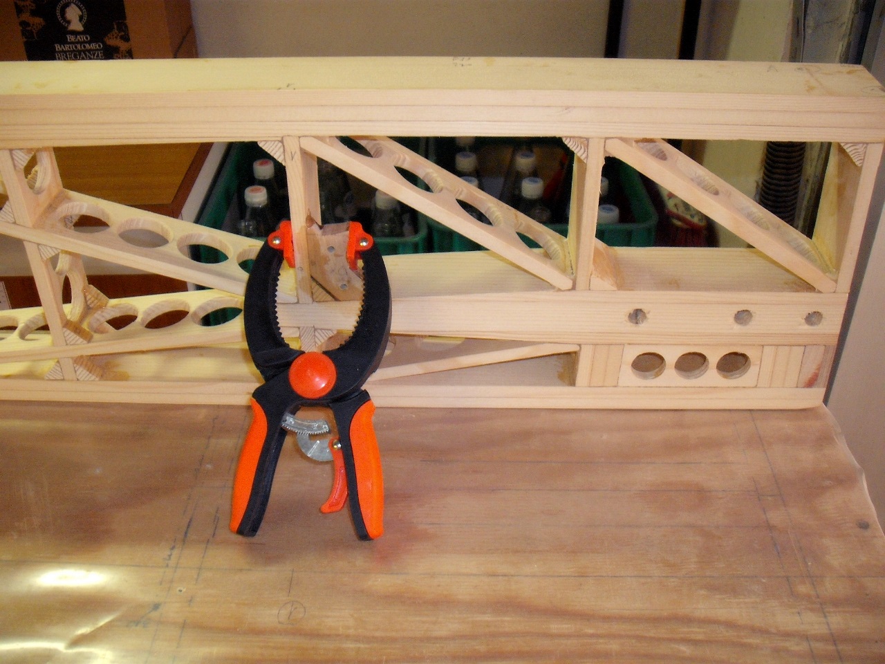
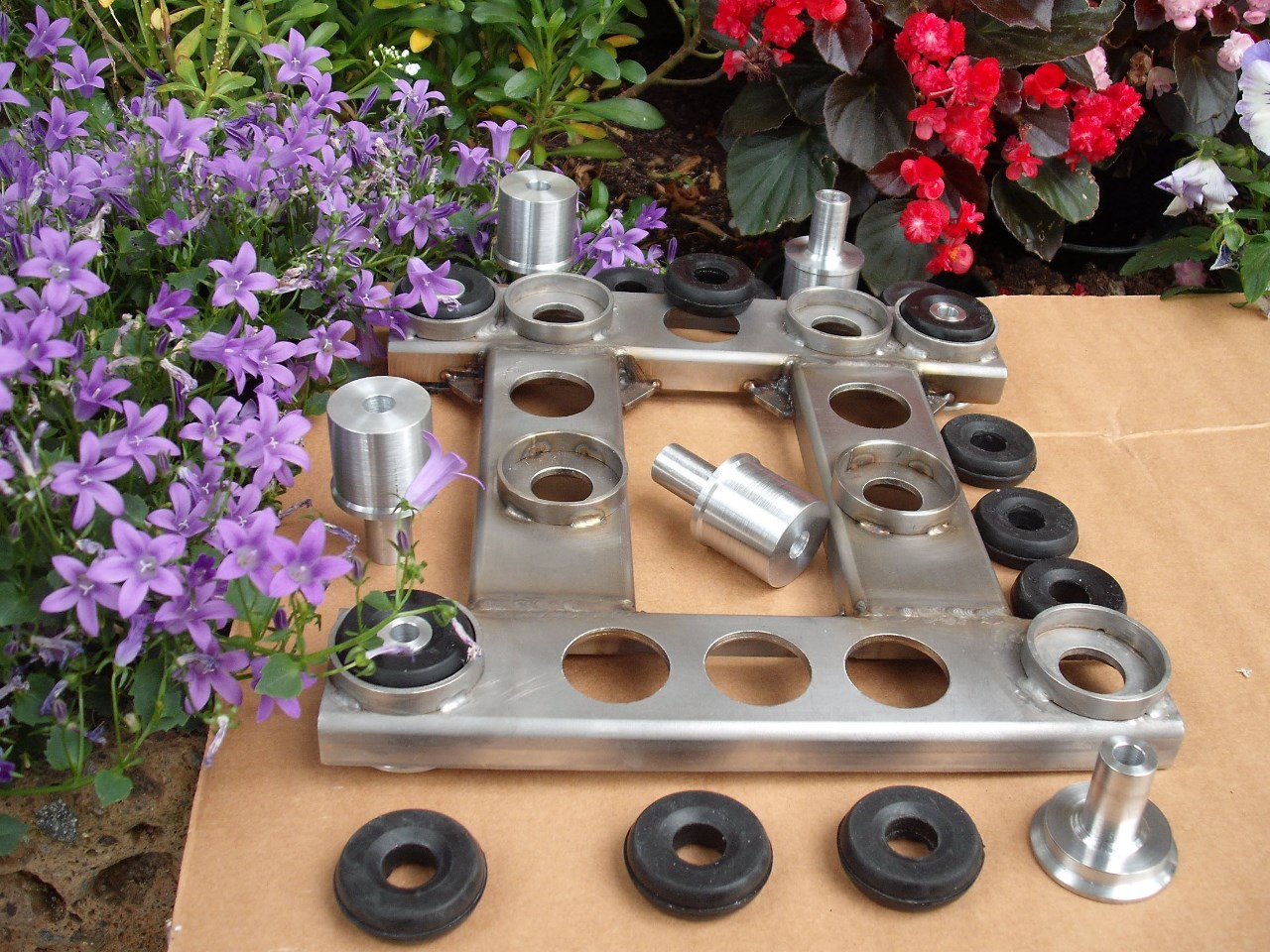
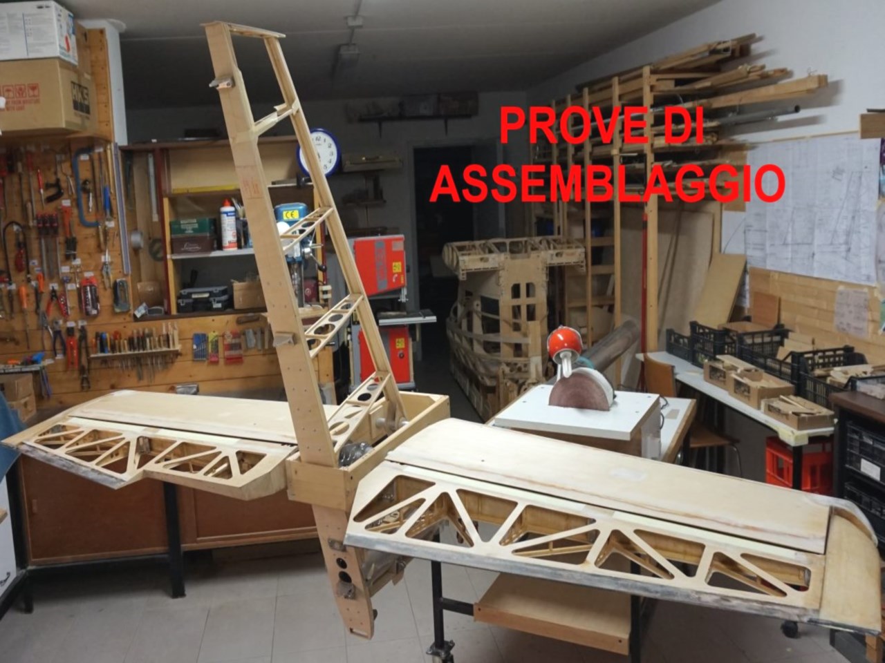
Prove di assemblaggio
-
-
-
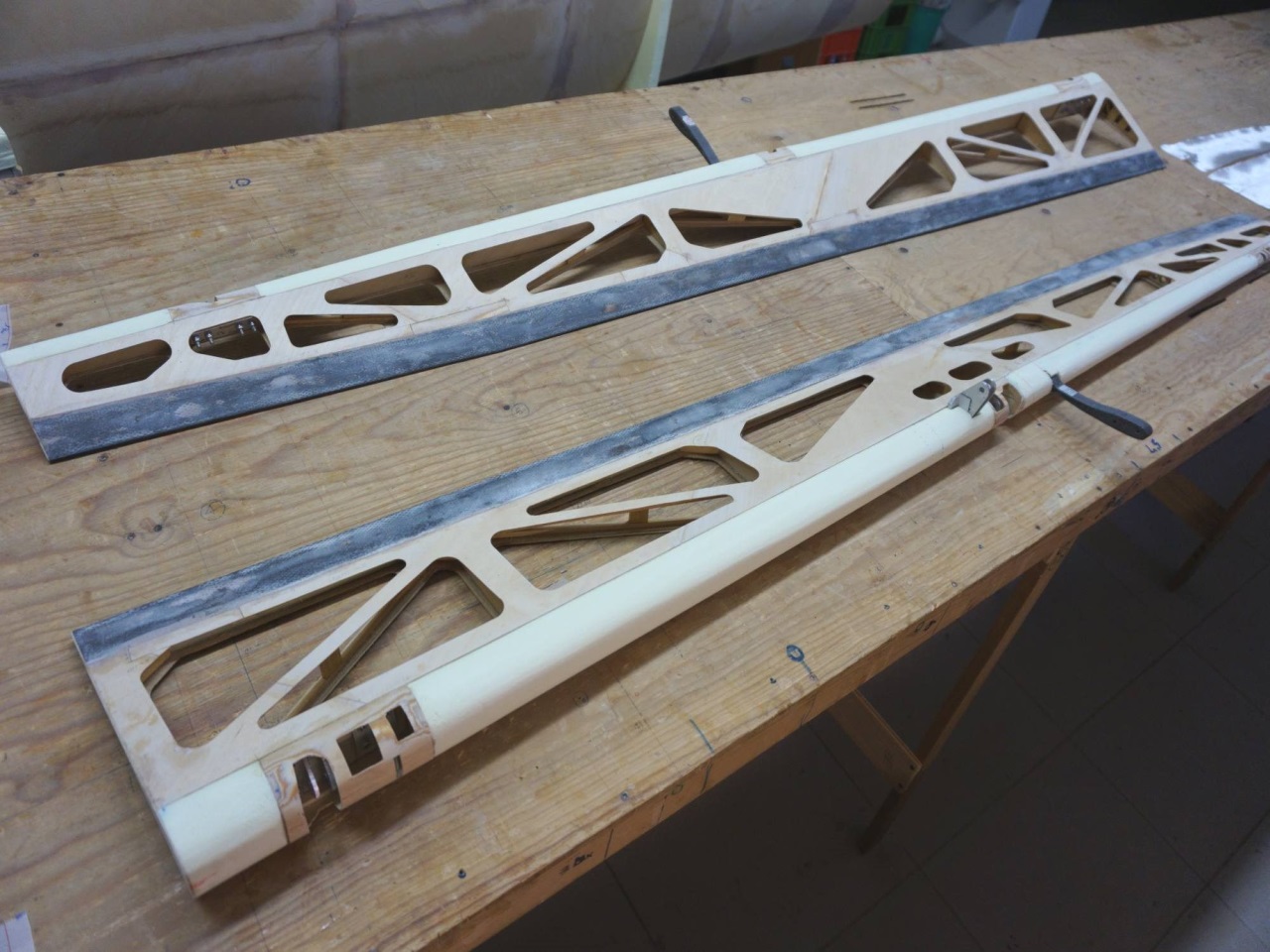
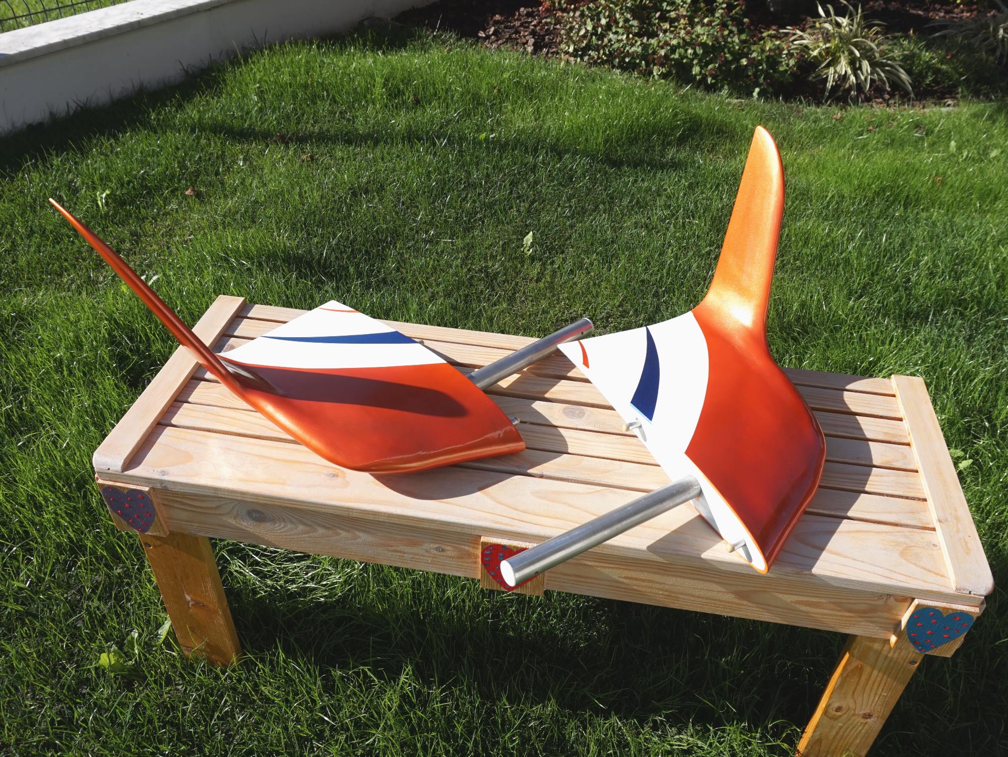
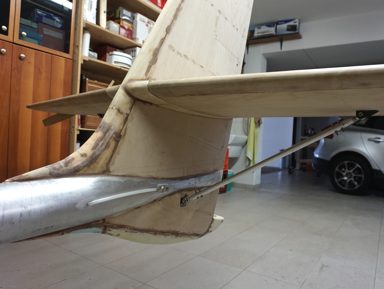
Tailplanes construction
-
-
-